With the rapid deployment of security surveillance, Industrial IoT (IIoT), and 5G micro-base stations, PoE (Power over Ethernet) technology has become a standard in modern network architecture. This article provides a deep dive into PoE working principles, core PD (Powered Device) circuit structures, and the evolution of IEEE 802.3 standards. We will also focus on engineering best practices for building high-reliability surge protection using TVS and GDT components.
1. What is PoE Technology?
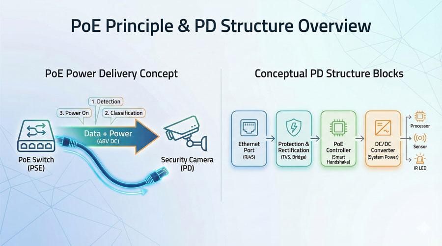
PoE technology allows for the delivery of stable DC power over existing Category 5/6 (Cat5/Cat6) Ethernet cabling simultaneously with data transmission.
From an engineering perspective, PoE is more than just “eliminating a power cable.” It is an intelligent power distribution protocol that enables distributed power supply and remote management in complex wiring environments.
2. Evolution of IEEE 802.3 Standards: From “af” to “bt”
Before selecting hardware, it is critical to understand the power limits of different standards. As technology has evolved, supported PoE power has increased from the original 15.4W to over 90W.
| Standard | Alias | Max Output (PSE) | Min Power Available (PD) | Pairs Supported | Typical Applications |
| IEEE 802.3af | PoE (Type 1) | 15.4W | 12.95W | 2-pair | IP Phones, Basic Cameras |
| IEEE 802.3at | PoE+ (Type 2) | 30W | 25.5W | 2-pair | PTZ Cameras, Dual-band APs |
| IEEE 802.3bt | PoE++ (Type 3) | 60W | 51W | 4-pair | Video Conferencing, Smart Lighting |
| IEEE 802.3bt | PoE++ (Type 4) | 90W | 71.3W | 4-pair | 5G Micro-stations, Industrial Displays |
3. PoE Supply Logic: The PSE & PD “Handshake”
A PoE system is not a simple power output; it is a rigorous closed-loop control process. To ensure safety, the system must complete the following handshake logic:
1. Detection — Signature Recognition
The PSE outputs a detection voltage between $2.7V \sim 10.1V$ to check if the PD presents a characteristic signature resistance of approximately $24.9k\Omega$.
- Engineering Note: Detection is initiated by the PSE; the PD’s role is to accurately “present the signature” in response. If the resistance does not match, the PSE identifies it as a non-PoE device and refuses to supply power.
2. Classification — Power Budgeting
The PSE increases the voltage to $14.5V \sim 20.5V$ and measures the current feedback from the PD to determine its Class level. This dictates the power budget the PSE must reserve.
3. Start-up
Once classification is successful, the PSE rapidly ramps up the voltage to approximately 48V (typical operating range: $44V \sim 57V$). Under the “bt” standard, the voltage range may be wider to compensate for line loss at high power.
4. Monitoring & Disconnection
The PSE continuously monitors the PD’s current status. If the PD is disconnected or its power consumption falls below the maintenance threshold, the PSE cuts power within 300-400ms to prevent damage to non-PoE equipment if re-plugged.
4. Analysis of Core PoE PD Circuit Modules
A high-performance, engineering-grade PD interface circuit typically consists of the following modular path:
1. RJ45 Interface & Magnetics
The RJ45 interface is the first point of entry for transient interference. Magnetics (Network Transformers) are responsible for signal coupling and isolation, while the Center Tap structure is used to inject or extract the supply current.
- Caution: Transformers must have sufficient DC bias capability to prevent magnetic core saturation caused by the supply current, which would degrade data communication quality.
2. Bridge Rectifier
Since PoE may use Mode A (Endspan) or Mode B (Midspan) and polarities may be reversed, the PD must include a bridge rectifier for polarity correction.
- Optimization: In high-power designs (e.g., 802.3bt), it is recommended to use an Active Bridge (MOSFET-based)instead of traditional Schottky diodes to reduce thermal loss and voltage drop.
3. PD Controller
The “brain” of the circuit, the PD Controller, handles the response to PSE detection/classification and manages the power path, including Inrush Current Limiting and Under-Voltage Lockout (UVLO).
4. DC/DC Power Conversion
Because PoE input is high-voltage (~48V), the downstream SoC usually requires 3.3V or 5V. Engineers typically employ Isolated Flyback or Active Clamp Forward topologies to meet the 1500Vrms isolation requirement of Ethernet standards.
5. Engineering Practice: Surge & Overvoltage Protection
Because PoE cables often run over long distances, they are highly susceptible to induced lightning surges or transient overvoltages during hot-swapping.
1. Differential Mode (Line-to-Line) Protection
Protects the downstream bridge rectifier and PD controller.
- Solution: Place high-power TVS (Transient Voltage Suppressors) at the front end of the bridge rectifier to clamp voltages within the PD controller’s safe operating window.
2. Common Mode (Line-to-Ground) Protection
Protects the transformer insulation and prevents the back-end circuit from being punctured.
- Solution: For outdoor or long-cable deployments, GDTs (Gas Discharge Tubes) should be introduced. By placing GDTs from the center tap or line pairs to ground, high-energy surges can be safely shunted to the earth.
- Design Detail: Ensure sufficient Creepage Distance (typically $\ge 2mm$) between Chassis Ground and Signal Ground (GND) on the PCB layout.
PoE technology achieves the efficient fusion of data and power through complex handshake protocols. For hardware engineers, understanding the entire link—from “Center Tap extraction” to “PD protocol response”—is the foundation for designing robust products. In practical applications, the proper configuration of TVS and GDT protection can significantly enhance a device’s survival in harsh electromagnetic environments.
FAQ
Q: Why must the PD controller present a $25k\Omega$ resistor during detection?
A: This is the “handshake signal” defined by the IEEE 802.3 standard. The PSE only supplies power when it detects this specific characteristic, preventing high voltage from being accidentally applied to standard network cards.
Q: Can I use only TVS without GDT in my protection circuit?
A: For strictly indoor, short-distance devices, TVS clamping is often sufficient. However, for outdoor APs or surveillance cameras, GDT is a necessary component to discharge the massive current from induced lightning.
Looking for Professional Circuit Protection Solutions?
If you face challenges in component selection for PoE interface protection, contact Boarden. Our technical support team provides one-stop testing and selection support, ranging from TVS arrays to high-voltage GDTs.